



Machining 6061 Aluminum to ±0.01mm: A Systems Approach
Published on Wednesday, 21. October 2026

Content Guide:Hitting ±0.01mm on 6061 aluminum isn't about machine accuracy—it's about controlling systematic errors. Learn a proven process: thermal deformation compensation, spindle runout checks, cutting force control, and SPC monitoring to turn post-inspection into process prevention and achieve stable batch
Making 6061 aluminum parts to ±0.01mm isn't about machine tool accuracy
6061 has good machinability and stable dimensions—no problem for ordinary precision parts. But once precision is pushed to ±0.01mm, the process window becomes much narrower. No matter how high the machine's rated accuracy is, it will still drift in batch production. At this point, what the process engineer needs to do isn't tuning parameters—it's holding down several systematic error sources: heat, runout, cutting force, and data monitoring. Here's the order based on what we've actually done.
Thermal deformation: measure it first, then talk about compensation
At the ±0.01mm level, thermal elongation of the spindle and ballscrew often eats up more than 30% of the error budget. Machining directly without measuring thermal characteristics is like adjusting tool compensation blindfolded.
A more reliable approach is to run the machine idle for eight hours before batch machining, record spindle axial elongation and Z-axis positioning drift, and build a "temperature rise—compensation amount" lookup table. Machines with temperature sensors can have the CNC directly adjust compensation values. Machines without this function aren't hopeless either—calibrate the Z zero point once on the first part, then spot-check with a standard part every two hours and manually tool length offset. Troublesome, but it works.
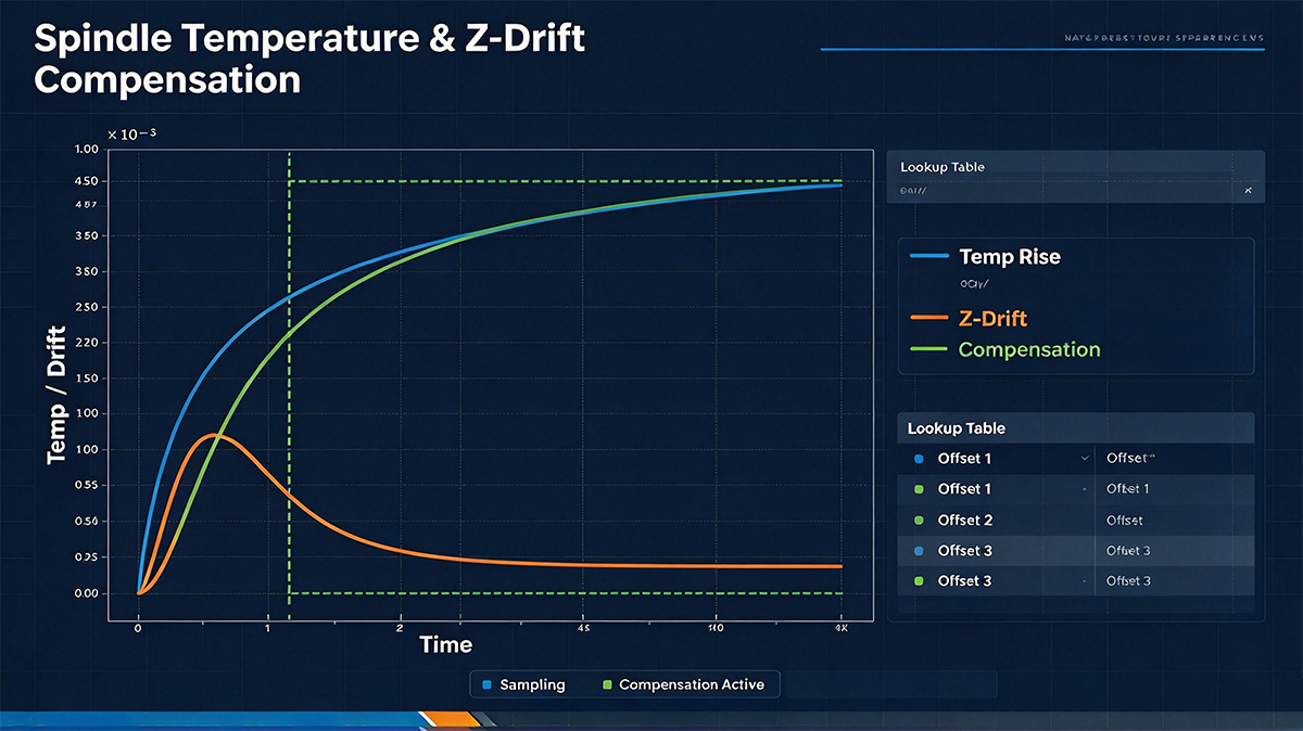
Spindle temperature rise and Z-direction drift compensation curve
Spindle runout and tool dynamic balance: check the taper first, then discuss tool holders
Keeping spindle radial runout within 0.005mm is the bottom line. If it's out of spec, don't rush to replace the spindle—check whether the taper is clean and whether the pull stud mating surface is damaged. Rule out these two spots before considering grinding and repair.
On the tool side, end mills below Φ6mm running above 12000r/min—the centrifugal vibration from unbalance will directly become sidewall chatter marks and dimensional scatter. Tool holders and tools should undergo G2.5 grade dynamic balancing as an assembly, and overhang should be kept within 4× diameter where possible. After loading the tool, check blade runout with a dial indicator—if it exceeds 0.008mm, change the tool holder or re-clamp. Don't settle.
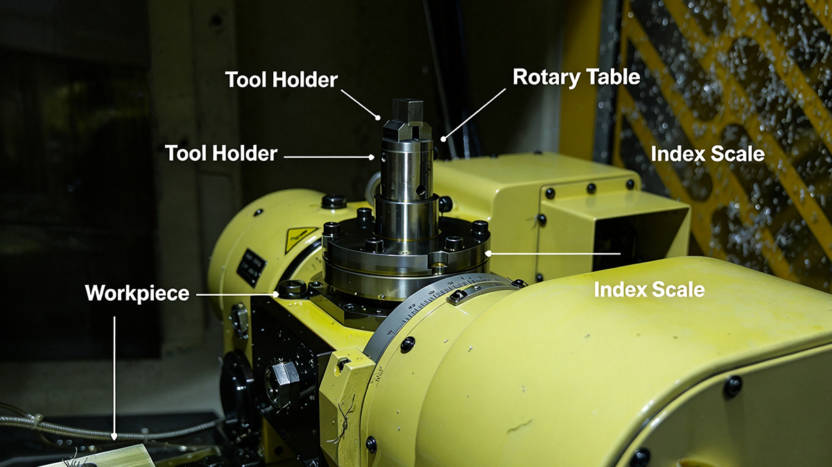
Tool assembly dynamic balancing and runout inspection
Cutting force: lock down finishing parameters, don't let operators adjust on the fly
6061 finishing follows the high-speed, small radial engagement, moderate feed-per-tooth approach—the goal is to suppress radial cutting force fluctuation. Finishing allowance should be controlled at 0.15–0.25mm, climb milling, constant radial engagement. For thin-walled parts, symmetric material removal or auxiliary support—no need to elaborate on that.
What is easily overlooked is the cutting fluid. Unstable concentration and flow rate can cause built-up edge as lubrication fluctuates, and dimensions will change abruptly along with it. There is another point: finishing parameters should be written into the locked program, and operators should not casually adjust the feed override on site. This rule looks rigid, but that is exactly how batch consistency is maintained.
SPC: Turn Post-Inspection into Process Prevention
For key dimensions—such as mating hole diameters and step heights—use Xbar-R control charts. Sample 5 pieces per batch, one group every two hours. Based on a ±0.01mm tolerance, keep the control limits within 50% of the tolerance band, with a CPK target of ≥1.33.
If 7 consecutive points rise or a single point exceeds 2σ, stop the machine and check thermal drift and tool wear. At the same time, record the correspondence between tool life and dimension deviation, and establish tool-change warning thresholds. Once this step is completed, inspection changes from "post-mortem autopsy" to "early warning."
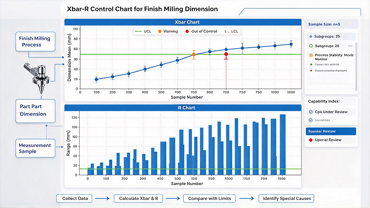
SPC control chart monitoring interface for finishing milling dimensions
In the End, It Depends on the System, Not the Parameters
To keep 6061 aluminum parts stable within ±0.01mm, no matter how perfectly individual parameters are tuned, it is not enough. Thermal deformation, spindle and tool condition, and cutting force fluctuation must be placed into the same controlled system, and then SPC data should be used to drive decisions. It is recommended to first build a thermal compensation lookup table and a tool runout inspection specification. These two are quick to implement and deliver obvious results, and then control chart monitoring can be promoted. Only when the closed loop of measure—compensate—control is running can batch consistency be guaranteed.
Previous:Sealing Challenges in 7075 Aluminum Valve Body CNC Milling
Next:No More/End